Cache Conscious Programming (quant dev notes)

In holding together an asynchronous messaging system such as a trading systems, the messaging queue reigns supremely important. The ring-buffer pattern is pervasive in these architectures. Similar principles appear well beyond trading infrastructure:
Linux io_uring submission/completion queues are built as lock-free ring buffers shared between user space and kernel, enabling direct enqueue/dequeue with minimal syscalls.
Network device driver rings (NIC Tx/Rx queues) use ring buffers to manage packet descriptors, allowing the NIC and CPU to communicate without locks.
Kernel schedulers and inter-processor interrupts rely on circular queues for tracking tasks and signaling between cores.
Logging subsystems (what we have been exploring)
Given their importance (in code, in learning, in interviews…) this is a good place to discuss the core ideas, micro-optimizations and cache conscious design of the ring buffer.
CPU Architecture
Here is a typical (well, my PC) processor topology of a modern CPU:
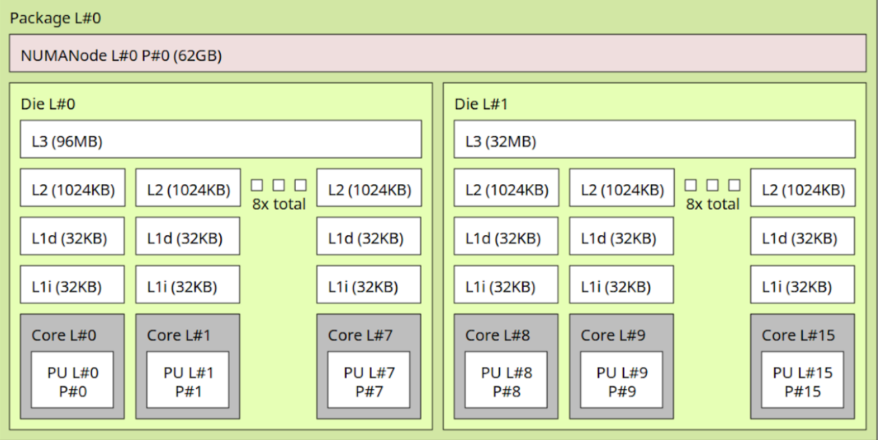
Modern CPUs are structured in a hierarchy of cores, caches, and interconnects. The diagram above shows a dual-die (two CCDs) package, the concepts generalize:
Core
Each physical core has its own private execution units and registers. This is where instructions actually execute. In the diagram, each “Core L#” box corresponds to one such physical core.Private L1 and L2 caches
Each core owns a private L1i (instruction) and L1d (data) cache, here 32KB each, plus a larger private L2 (often a few hundred KB to 1MB). These caches keep the hottest working set close to the core, minimizing round-trips to shared resources.Shared L3 cache (per die/CCD)
Cores in the same die (or “core complex” in AMD terms) share an L3 cache. This last-level cache (LLC) acts as both a victim cache and a directory: it tracks which core owns which line. If one core modifies a line, the LLC helps ensure other cores see the update.NUMA nodes and memory controllers
Each die connects to a slice of main memory. Together, the die + memory controller form a NUMA node. Accessing your “local” node is fastest; accessing memory attached to another die incurs extra hops through the interconnect.Interconnect fabric
When data needs to cross die boundaries, it travels over the on-package interconnect — Intel Mesh, AMD Infinity Fabric, etc. This path has higher latency and lower bandwidth than staying inside the same die.
Cache Coherence
When each core has private L1/L2 caches but shares data with others, cache coherence protocols ensure a consistent view of memory. A write to a cache line on one core requires invalidating or updating the copies on other cores.
Within the same die/CCD: the shared L3 (last-level cache) acts as the directory. Coherence traffic stays local and latencies are tens of nanoseconds.
Across dies/CCDs or sockets: traffic goes over the interconnect (Infinity Fabric etc.), adding tens of nanoseconds more.
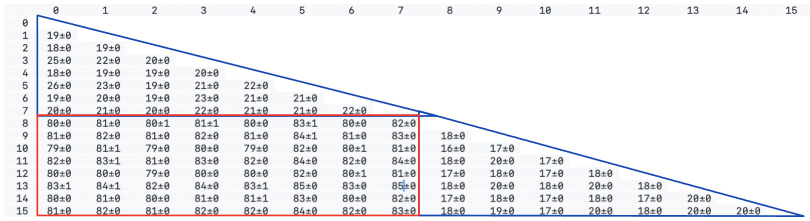
Here is the CAS (compare and swap) latency on a single shared cache line using the core-to-core tool on the processor topology above - you can see clearly two latency clusters (in blue) by their CCD, and the degradation in Cross-CCD cache coherence overhead (in red).