
Network Programming; Wire to Handler.
the journey of the binance trade packet

Intro Quant trading lectures are listed again for the following week.
Our previous work was on implementing fast inter-thread messaging libraries on the nanosecond scale in cpp;

We move on to a multi-part series on low latency network programming. Future posts will cover nanosecond-scale logging, and in-memory orderbook. The four parts - network client, logging/instrumentation, and orderbook logic is a nice grouping that any MFT/HFT would interface with.
This post - we will discuss the flow of data from the wire to the user buffer, and design the software components of a network client.
Low Latency Network Programming; RX/TX
A network program is any application that performs I/O across a communication channel between two or more machines. In almost all modern systems, this communication is expressed in terms of the operating system’s socket abstraction, which provides an API for transmitting and receiving byte streams.
The act of sending data from a local machine to a remote peer is referred to as TX (transmit). This operation involves user-space memory being passed to the kernel, which queues the data for eventual dispatch by the network stack. The reverse operation, receiving data from the network into user space, is referred to as RX (receive).
It is important to distinguish between two levels of execution in a modern operating system: user space and kernel space. User space refers to the part of the system where application code runs. It has restricted privileges and must interact with hardware and external resources via well-defined system calls. Kernel space refers to the privileged part of the operating system that can directly access hardware, manage memory, and schedule processes.
Network programs are designed around a specific communication goal. For example, a market data client receives inbound packets over TCP that encode order book updates, which must be parsed and processed with minimal delay. A trading engine, conversely, transmits outbound orders to an exchange gateway, expecting acknowledgements or fills in response. In both cases, RX and TX must be handled carefully to minimize latency and jitter.
In order for communication to succeed, both the sender and receiver must agree not only on the content of the message, but also on how it is transmitted and interpreted across the system boundary. This agreement is not confined to a single format or mechanism, but instead spans multiple layers of abstraction—from how bytes are encoded in physical signals to how messages are interpreted by the application.
This layered structure is formalized in the five-layer network stack, a conceptual model that decomposes the task of network communication into distinct stages. Each layer is responsible for a well-defined aspect of the transmission process, and interacts only with the layers directly above and below it. This separation of concerns makes the system modular, debuggable, and tunable.
Layer 1: Physical — Describes how raw bits are physically transmitted over a medium such as copper wire, fiber optics, or radio waves. It defines voltage levels, timing, and encoding schemes, and is implemented entirely in hardware (e.g., network interface cards and transceivers).
Layer 2: Data Link — Groups raw bits into frames and defines local delivery between directly connected devices. This layer handles hardware addressing (e.g., MAC addresses), error detection, and basic flow control. Ethernet is the most widely used Layer 2 protocol today.
Layer 3: Network — Handles routing of packets across multiple physical links. It provides global addressing via IP (IPv4 or IPv6), and handles packet fragmentation and reassembly if the message is too large for the link. This layer is implemented in both hardware (e.g., routers and NIC offloads) and software (e.g., the Linux kernel’s IP stack).
Layer 4: Transport — Provides end-to-end communication between processes on different machines. It introduces the concept of ports and manages sequencing, acknowledgments, retransmissions, and congestion control. TCP and UDP are the two dominant transport protocols. The logic for these protocols resides in the operating system kernel.
Layer 5: Application — Defines the meaning and format of messages exchanged between programs. Protocols at this layer include HTTP, WebSocket, FIX, and custom binary formats used in trading or data feeds. Application-layer protocols are implemented entirely in user space.
Each layer adds its own header to the payload it receives from the layer above, forming a nested structure. At the receiver’s end, these headers are parsed and stripped in reverse order.
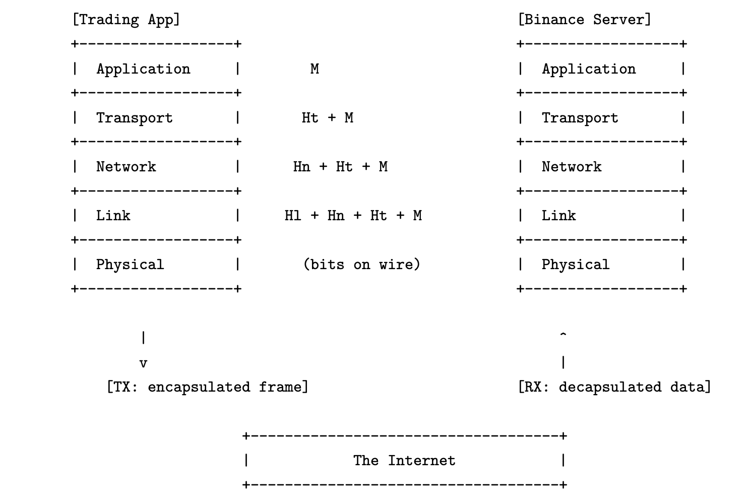
Intentionally, The Internet in figure above abstracts away a sequence of intermediate devices that forward the packet from sender to receiver. These include Layer 2 and Layer 3 devices such as switches and routers:
Switches (L2) — Forward Ethernet frames based on destination MAC address. They operate within the same broadcast domain.
Routers (L3) — Forward IP packets based on destination IP address. They connect different subnets and perform a variety of tasks we shall blissfully ignore.
Transit/Backbone — These may include MPLS switches, BGP-speaking routers, load balancers, or NAT devices, especially as the packet crosses administrative domains (ISPs, IXPs, cloud edge). In practice, the route may traverse dozens of physical hops.
For a full pedagogical treatment of these forwarding paths and control protocols, refer to Computer Networking: A Top-Down Approach by Kurose and Ross.
From the perspective of an application developer writing latency-sensitive code, such as a high-frequency trading system, the relevant abstraction is not the entire five-layer stack but the software-visible boundary between user space and the kernel. While it is well and possible that a high-frequency trading enterprise optimizes over the entire stack, our perspective as a quantitative developer focuses on L3–L5, as will our exposition in this chapter. Besides, the modularity of the stack implies that the optimization of one layer is independent of the other, such that techniques employed here are additive to optimizations at the lower layers.
With this philosophy in mind, we will go in-depth into the design and implementation of a low-latency TCP client. Extension to UDP protocols should be fairly straightforward.
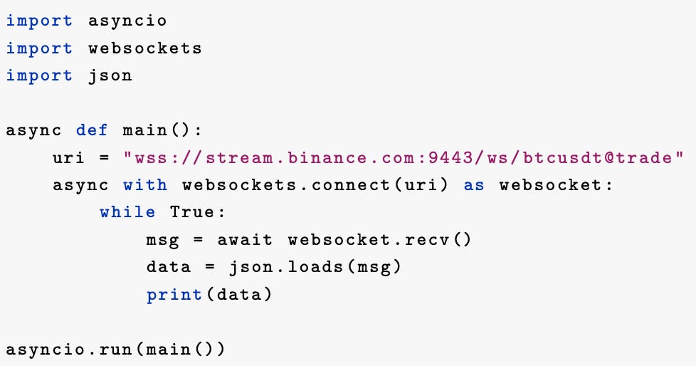
The TLDR of this chapter is this: we will go in-depth as to what happens behind the scenes when an innocent program such as the one in code snippet below is run – we will write the entire client from scratch in C++ using POSIX sockets, discuss where latency is introduced, and the alternatives/design choices available to the network programmer as solutions.
Where suboptimal choices are made, leaving room for improvement, we will give annotations on improving the implementation – our focus lies on optimizing the RX hot path. Minimally, understanding the control flow of a network packet is the first step to optimizing it.
A couple thousand lines of code will be written, and tens of μs of latency will be shaved, against network clients such as Python’s websockets and C++’s Boost clients.
If this sounds like a daunting task, that makes two of us. If that sounds like an unworthy endeavour, that makes one of you, and perhaps this is not the series for you. We shall proceed anyhow.
A Packet Walk
What underlies those statements?
DNS and Connection Setup
Before any socket is opened, the hostname stream.binance.com must be resolved via DNS. DNS resolution is the process of translating a human-readable domain name into an IP address that identifies the destination host on the Internet.
This is typically performed in user space by the C library via getaddrinfo(), which may consult local caches, /etc/hosts, or issue a UDP query to a recursive resolver (e.g., 8.8.8.8) over port 53.
Following DNS resolution, a non-blocking TCP socket is created. The syscall socket(AF_INET, SOCK_STREAM, 0) returns a file descriptor, an integer handle that refers to a kernel-managed socket object. This object tracks TCP state, transmit/receive queues, timers, and configuration (e.g., congestion control algorithm).
The client then initiates a three-way handshake by calling connect(), which instructs the kernel to send a SYN packet with a chosen sequence number and negotiated TCP options (MSS, window scale, SACK). The kernel transitions the socket state to SYN_SENT, awaits a SYN+ACK response from the Binance server, and replies with an ACK to complete the handshake. Once this exchange finishes, the socket state becomes ESTABLISHED, and the connection is ready for bidirectional data transfer.
All of the TCP handshake occurs inside the kernel. The user process that initiated connect() must wait for completion. In synchronous code, this blocks the thread. In asynchronous code, the file descriptor is registered with a readiness notification mechanism such as epoll, select, or io_uring, which allows the process to efficiently wait for events (e.g., socket is writable, readable, or has errors) without busy looping or sleeping.
TLS Handshake and Cipher Agreement
After TCP connection is established, the user WebSocket library initiates a TLS handshake because the URI scheme is wss://. This involves several back-and-forth messages including:
ClientHello, specifying supported TLS versions, ciphers, and extensions.
ServerHello, selecting the cipher and sending its certificate chain.
Key exchange, typically via ECDHE or RSA, followed by Finished messages.
All of this is encrypted and layered on top of the TCP stream. The TLS state machine and cryptographic operations are implemented in user space (e.g., OpenSSL, BoringSSL), though in some systems can be offloaded to the kernel (via kTLS) or to NICs that support TLS acceleration.
Once the handshake is complete, both parties derive symmetric keys and the connection enters encrypted mode.
HTTP Upgrade and WebSocket Negotiation
The client then sends an HTTP/1.1 request to upgrade the connection to a WebSocket session. This is a plaintext protocol negotiation that occurs after the TLS handshake, but still over the same encrypted TCP stream. A typical request looks like the following:
GET /ws/btcusdt@trade HTTP/1.1
Host: stream.binance.com:9443
Upgrade: websocket
Connection: Upgrade
Sec-WebSocket-Key: x3JJHMbDL1EzLkh9BhXGDw==
Sec-WebSocket-Version: 13
The Sec-WebSocket-Key is a base64-encoded random nonce; the server replies with a hashed version of this to prove compliance with the WebSocket protocol.Sec-WebSocket-Version must be 13, as mandated by RFC 6455.
The Binance server responds with a 101 Switching Protocols status line, and includes its own headers acknowledging the upgrade:
HTTP/1.1 101 Switching Protocols
Upgrade: websocket
Connection: Upgrade
Sec-WebSocket-Accept: HSmrc0sMlYUkAGmm5OPpG2HaGWk=
From this point onward, the client and server switch to the WebSocket framing protocol, encapsulating application data into WebSocket frames layered over the TLS-encrypted TCP stream.
Receiving Trade Messages
Some attention is warranted here, as this is the core of where our low-latency design choices make a difference.
The line msg = await websocket.recv() enters a long-lived receive loop. On the network wire, Binance pushes trade messages as UTF-8 encoded JSON payloads framed into WebSocket text frames (opcode 0x1), layered over a TLS-encrypted TCP stream.
The full data path for a single message looks like this:
Binance serializes a trade update (e.g., price, size, timestamp) as JSON.
This is framed into a WebSocket text frame, encrypted via TLS, and written to the server’s socket send buffer.
The kernel TCP stack segments the stream and hands each segment to the NIC, which performs DMA (direct memory access) from kernel memory to NIC TX buffers, transmitting the packet onto the wire.
The packet traverses multiple L2/L3 hops — The Internet — before arriving at the client’s network interface.
The client NIC receives the packet and performs DMA into a kernel receive ring buffer, typically mapped by the NIC driver.
The kernel TCP stack reassembles the byte stream from incoming segments, verifies sequence numbers and checksums, and writes the result into the socket’s receive buffer. This buffer is exposed to user space via standard syscalls such as
recv()or via asynchronous interfaces likeepoll()orio_uring.TLS decryption
In the default case, user space calls
recv()to read encrypted bytes from the socket into a TLS library such as OpenSSL, which performs decryption and returns plaintext data to the application.If kTLS is enabled and supported, TLS record decryption is performed in-kernel. The kernel writes decrypted data directly into the receive buffer, so the WebSocket library receives plaintext via
recv(), bypassing the TLS library entirely.If TLS hardware offload is available and configured, decryption may be performed on the NIC itself, which DMA-transfers already decrypted data into kernel memory. This is a more advanced form of kTLS.
The WebSocket library parses the frame headers, extracts the UTF-8 encoded payload, assembles frames into a complete message and passes it to the user’s handler.
Note that WebSocket framing is a logical application-layer concern and is entirely orthogonal to TCP segmentation; a single WebSocket frame may span multiple TCP segments, or multiple frames may arrive within one TCP segment.The payload is decoded from UTF-8 and parsed as JSON, producing a Python
object/ C++structcontaining the trade data.
The data is passed many times in memory in the worst case.
First, the NIC performs a zero-copy DMA into the kernel’s receive ring.
The kernel then copies the data into the socket receive buffer.
From there, the user process calls recv(), copying encrypted bytes into OpenSSL’s input buffer. OpenSSL decrypts this into a separate plaintext buffer.
The WebSocket library then parses the plaintext into its own frame buffer, which the user handler finally copies or deserializes into application-owned memory.
The path just described involves one DMA and five CPU-driven memory copies, each introducing latency and cache pressure.
The goal of low-latency network engineering is to reduce or eliminate these copies where possible via kernel TLS, registered buffers, or zero-copy parsing, as well as tuning kernel socket configurations, choosing appropriate event-driven I/O strategies.
Our mission had three goals; to discuss
(i) the flow of data from the wire to the user buffer and identify potential areas for optimization.
(ii) design choices for writing low latency features of a network client and
(iii) to implement a subset of the features in (ii).
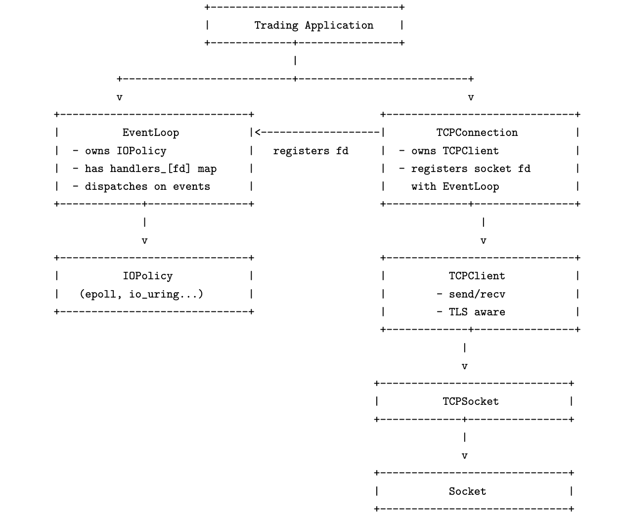
We have achieved (i) in this post, and designed the architecture of the components in a network client. Now that the layout of our software components is clear, we may explore the design choices in each of these components separately.
Look forward to seeing you in the next part!